
FiveSquare
5x5 LED matrix
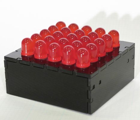
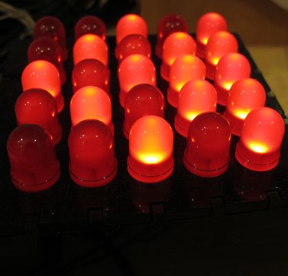
FiveSquare is a PIC16F628/16F648 project that uses twenty five LEDs arranged in a five-by-five square. The LEDs are mounted on a laser-cut case, which also holds the circuit board. The PIC application animates the LED display.
Leave comments on the blog post
The Animator application, the LED animation editor used to create all of the animations, is now available here.
Downloads are available at the bottom of the page
PIC Assembly Code and LED Animations
The PIC program shows a series of animations in a continuous loop. The animations are stored as small tables and are encoded in one of three ways: as frame-by-frame, as sliding strip, or as pixel list. For frame-by-frame, the table lists each frame of the animation. The apps shows a frame for a certain amount of time, then shows the next frame. This is the most flexible format, but also uses the most data (4 bytes per frame). The sliding strip stores the animation as one long 'image', which is slid across the 'display'. The sliding can be either horizontal or vertical. The pixel list encoding stores ta list of pixel (LED) numbers. When the animation runs, each pixel in the list is lit and, after a certain number are on, they are turned off in the same order.
The Dispatching page explains how the app gets the data for each animation.
When you build the project (with Microchip's IDE), you will get a number of warnings about 'crossing the page boundary'. This is expected. Some of the tables that contain the animations cross the page boundary, but the code that jumps into the table adjusts the program counter registers appropriately so that everything works as needed
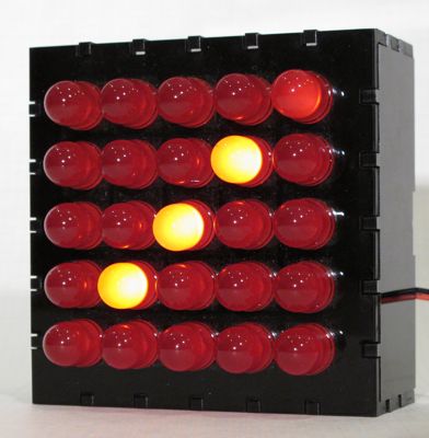
Here are three example animations.


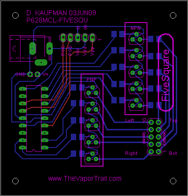
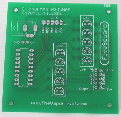
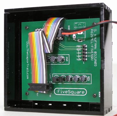
PCB Layout and LED Wiring
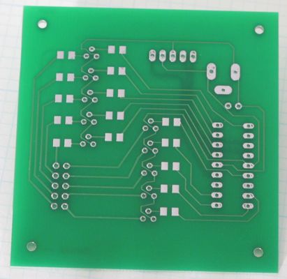
The PCB is two-sided, but can be made one-sided with three wires. The three wires are for the in-circuit programming, so these are not necessary if you program the PIC before placing it in the socket. To save space I used surface mount resistors.
I used BatchPCB to make the board. BatchPCB's prices are relatively cheap, because they wait until they have enough designs to cover a large board before sending the files to be made into boards. The benefit is the price is low, but it does take a while for the boards to show up.
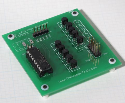
The connection for the LEDs is a 10-pin (2x5) header on the board. I like this because I can easily try different LEDs on the same board. One of the images below shows the board with offsets as 'feet'. This board sits on my workbench and is not placed in the case.
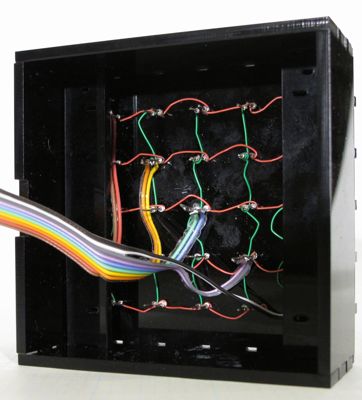
The LEDs are wire-wrapped in a matrix arrangement. I attached a ribbon cable with a 10-pin (2x5) socket that matches the 10-pin header on the board. You could easily solder the ten wires from the LED matrix directly to the board.
Case
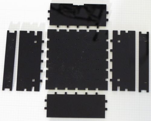
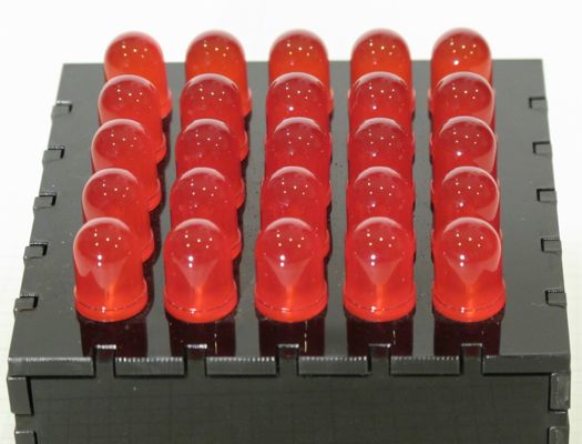
The case was cut by Ponoko out of 3mm black acrylic. The sides and tope are not glued, but are held together with pressure.
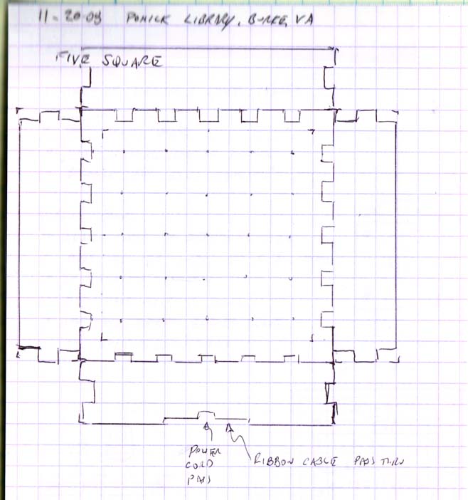
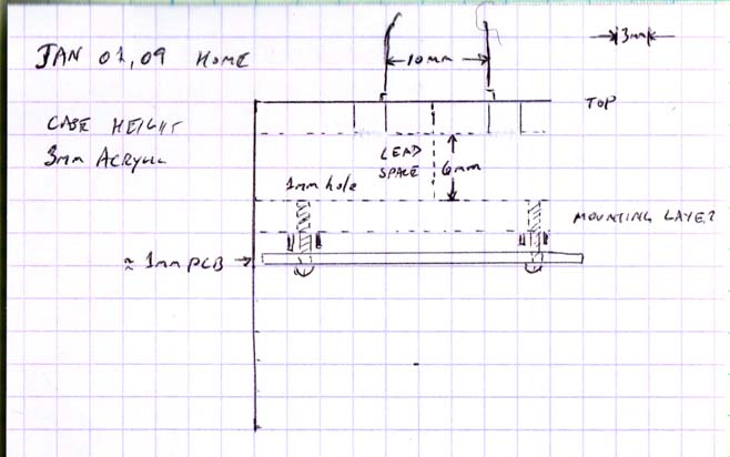
Along each top edge I wanted five tabs and slots to line up with the five rows and columns. Also, since I wanted a place to mount the circuit board, I had to figure out how far it needed to be from the top. One of my notebooks sketches (below) shows how I worked that out, as well as the exact size for the circuit board.
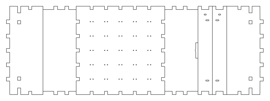
At the bottom of this page you can download the SVG file for the case. This diagrams in this file are for Ponoko. For Ponoko the width of the lines for the laser to follow should be 0.03mm. The problem with this width is that it does not render unless you zoom into the diagram .. a lot. Or you can use Inkscapes "outline" view (View > Display mode > Outline) to show all of the lines at 1 pixel wide.
Also at the bottom of the page is the actual file I submitted to Ponoko. This file is for the "P2" size from Ponoko, which is 15.1 x 15.1 inches (384 x 384 mm). On this sheet I could include four of these cases plus a few other projects and ideas. The total cost for this was $56.08 (materials: $9.86, making: $22.77, shipping and handling: $23.45 {from New Zealand}).
Notebook sketches
These are the sketches from my notebook. If you right-click, you should be open these in a new window at full size. (They are currently at 50%.)
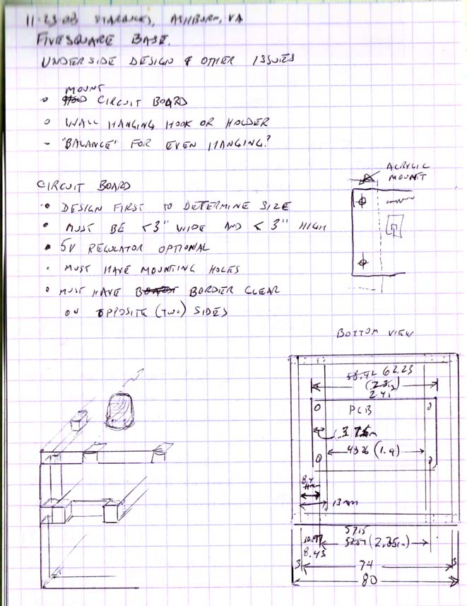
Parts and Layout
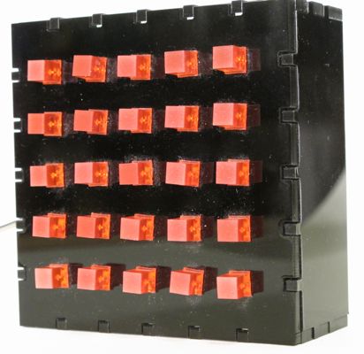
Assembled Project
Blog posts
Original
FiveSquare: A 5x5 LED MatrixDownloads
PIC Assembly and Microchip Project fileFiveSquare.hex file
EAGLE files
These next two files are vector diagrams for a laser cutter. The line width is very, very small, and and the lines will not be visible unless zoomed-in or shown as 'outline' in Inkscape.
Inkscape (SVG) Case diagram
SVG file submitted to Ponoko and ordered