
Low-Profile Benchtop Power Distribution
Introduction
I usually have many breadboard projects on my workbench. I wanted to find a convenient way to connect power to the breadboards. I had an idea to take a 40-pin connector and use it as an "outlet" with 20 sockets and making miniature "extension cords" with 2-pin headers on each end.
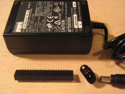
I picked up the parts at a surplus electronics store. Since all of my projects are typically PIC microcontroller, TTL, or something else in that voltage range, I decided to use a single voltage 5V 2.5A supply that had a simple connector. I found a matching jack and a 40-pin IDE connector.
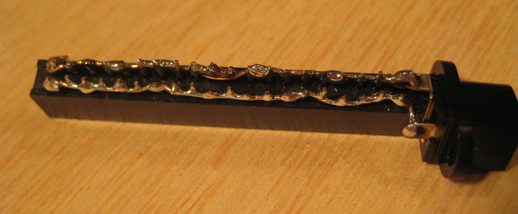
I soldered all of the pins on one side together with a wire and did the same for the other side. Then, each of the wires were soldered to the power jack. I placed the jack as close as possible so that the entire "power strip" would be a single unit and the jack would not flex the wires.
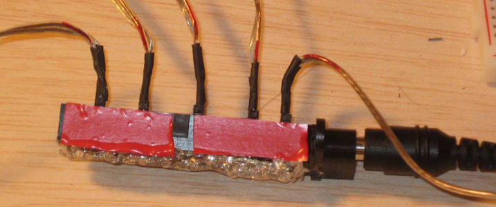
After soldering, I used hot glue to cover all of the exposed pins and wire. I put red electrical tape on one side to show the positive side.
To connect the power to the boards I created small "extension cords". I used speaker wire, because I liked the way the wires were attached to each other. At both ends I soldered on a 2-pin header. I used heat shrink tubing to both cover the solder joints and to give the connection a little extra strength.
I should have waited until I got some red heat shrink tubing to finish this. Instead of waiting I used a red Sharpie to mark the "positive" (really, just the same) side of each end.
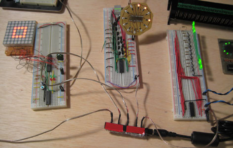
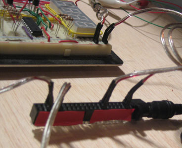
Here I am testing the "power strip" with various boards to make sure everything still works.
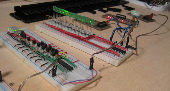
Once nice thing about the extension cords is that you can use them to connect the power from one boards to power another board.